Pages

Thursday, 27 June 2019

Doris B - Diodes and dynamometers

If simplicity is a virtue then my first attempt at making a dynamometer could be regarded as sinful.  This more successful machine consists of a wooden pulley bolted to a bicycle hub generator.  The pulley is turned by fishing line attached to a weight, a 10 watt resistor acts as a load.  An Arduino measures the voltage across the resistor and senses the rotational speed as the weight falls, all this provides enough information to estimate the input and output power which in turn suggests the efficiency of the system.


The generator turns out AC but to charge batteries it is necessary to convert the output to DC.  When developing anything, a good rule is "first make it work, then make it work better".  Initially, a standard silicon bridge rectifier was used.  This had a voltage drop across the diodes of 0.7 - 0.8 volts.  I flirted with the idea of smart diodes based on mosfets but this required greater knowledge and skill than I possess.  A simpler alternative was a bridge rectifier made up of Schottky diodes.  These have a voltage drop of around 0.2 volts.  The effect was to increase the power available to do something useful as shown in the graph below:

For a given speed, the output is roughly 0.3 watts higher with the Schottky diodes, they also increase the system efficiency by about 10%.

The diodes are rated at 100 volts to accommodate the generator when it goes open circuit.

The next step is to use the dynamometer to investigate the use of pulse width modulation to manage the load.  The objective is to use the power curve to optimise the relationship between the rotor and the generator.


Saturday, 22 June 2019

Doris B - The experience box

I was in a bar chatting to one of my sons (he's 31).  There's some overlap in our work experience and we were talking about product development and he came up with the description "first we make things, then we break them" which is a variation on one of my mantras "if you want to learn fast, make mistakes fast".  This gives me great faith in the next generation.


Oddly, I've just cleared some space in my work room by dumping less than successful bits of wind turbine into a box.  This includes three rotor designs, two generator, several attempts at making drag buckets and does not include several Meccano constructions which have been dismantled.  Work had been progressing steadily but I came to the conclusion that the generator I was using was probably 15 years old albeit in good order.  It might have benefited from being stripped down and the bearings cleaned but I was uncertain about the state of the magnets.  As I'm about to invest some time and energy in this project, I thought it would make sense to start with a brand new one.  The new one is slightly smaller and lighter than the original, so the bucket carrier and the dynamometer ring will have to be remade.  A slightly tedious task but an opportunity to remove some defects.


The dynamometer is very simple, it consists of a length of fishing line wound onto a pulley, the line runs through a pulley/block on which a weight is hung.  As the weight descends, it turns the generator.  The Arduino works out the rotational speed and the energy generated, the rotational speed is also a measure of how fast the weight is falling allowing the input energy to be estimated which in turn allows the efficiency to be estimated.

Monday, 3 June 2019

The Kettle half full

I'd like to say that that this post was based on a rigorous analysis of a vast database, sadly it's based on four meter readings, but lack of data should not get in the way of a good argument.

Much of the debate on emissions focuses on tax and technology and both have a role to play but the elephant in the room is behaviour.  We choose to get on aeroplanes, we choose to drive cars with big petrol engines (like many young engineers I lusted after cars and motorbikes), on a hot Texas day who can resist the switch on the aircon and we often overfill the kettle.

Engineers are generally trained to get a result with the minimum effort, the logic that makes a better jet engine also applies to making tea, you should use the minimum amount of energy, as an undergraduate I got into the habit of filling my mug from the tap and tipping it into an empty kettle, something I still do.  The most common reaction from family, friends and colleagues is that this weird and unhygienic, a response to the latter is that a kettle is also a steriliser.

Recently our 1.7 litre kettle became the logical equivalent of a bucket and was replaced by a 1 kw 0.85 litre version, it still gets overfilled but by half a litre not a whole one.  It's not obvious if this explains our reduced our electricity consumption (and emissions) but it did not increase them:


In England, most kettles ceased to be zero emission devices when coal became the dominant domestic fuel in the 18th  century.  Most cooking ranges were lit in the morning and kept burning into the evening, which is why the kitchen was the centre of family life because it was the warmest room, a kettle left on the hot plate would always provide water for tea or coffee, there was no saving of fuel by doing otherwise.  The modern kettle also provides a similar supply of hot water but unlike the coal fired range the energy consumed is proportional to the volume of water being heated.

Kettle on a coal range (credit: Brighton Museums)
The zero emission kettle made an appearance during 19th century in the reception rooms of grand houses.  The downside of having a large house was that the kitchen was often in the basement, by the time a maid had carried the kettle up a flight of stairs, along corridors and halls to the sitting room where the lady of the house was entertaining, the water was no longer hot enough to make a decent cup of tea. The solution was a table top charcoal stove.

Sunday, 2 June 2019

Doris B - Carpentry and Computing

The design is slowly moving forward. I’ve messed with small wind turbines before, but Doris B is an attempt to create some design rules. The objective is to get an output of 2.5 Watts in a 5 m/s wind. The current rotor is 0.7 metre in diameter with six buckets and s of the drag type. It’s had a couple of runs without instrumentation, but eyeballing the rotor suggests that its operating speeds are between 50 and 150 rpm. The current activity is figuring out the electrics and creating a functional data logger.


Almost any design of turbine will turn in a 10 m/s wind, but at 5 m/s the available energy is about 70 Watts/m2, which is not a lot, thus small things become important. The first attempt at creating a power box used a basic silicon bridge rectifier, smoothing capacitor and a voltage regulator. The voltage drop across the diodes in the rectifier was approx. 0.7 – 0.8 volts which is about 10 – 15% of the voltage of the generator, the rectifier will shortly be replaced with four Schottky diodes which hopefully will have a voltage drop of around 0.3 volts. The voltage regulator did nothing useful, three partially discharged Ni-Mh cells drew around 300 mA without the voltage regulator which is roughly a charge rate of 0.15 abd a reasonable working level. Removing the regulator cleaned up the power curve, which currently looks like this:


Part of the design is to match the power drawn by the generator to that generated by the rotor. With no load, the generator turns freely in a light wind. place a 10 ohm resistor across the terminals and it seems likely that it will cease to do so. Experiments with pulse width modulation of the load suggest that this is a potentially efficient way of optimising the relationship between the rotor and generator.

My love of the Arduino is growing steadily. Over my professional life, computing power has increased dramatically, CPU speeds are now measured in GHz, RAM in GB and storage (which is not necessarily local) in TB. The Arduino Nano was originally purchased as an analogue to digital converter for a Raspberry Pi, however, with experience, I’m realising the capability of the Nano. This should not be be surprising, my first programming experience was on an ICL 1900 which if I remember correctly had 16 Kb of magnetic core storage, static data lived on punched cards and if that was not enough the only option was a tape drive which required serious negotiating skills to access. Those machines were a great opportunity and so are the Arduinos. If you are used to working with GB databases, 1 Kb of EEPROM does not seem a lot, but it’s enough and there is the potential of IoT to explore.

Footnote – A month ago, my laptop died, it was expedient to hook up a Raspberry Pi. At some point I will have to replace the laptop, but the Raspberry Pi is doing fine, I have not done any serious analysis, but the energy I use whilst messing with computers might have dropped by 0.5 kwh/week (a guess)


Friday, 10 May 2019

Clouds and Irradiance from the sky


This was quick-and-simple study to look at the distribution of solar irradiance under a cloud sky.  The intention was to get some insight into the mounting of solar panels.  Under a clear sky, the greatest output is obtained by pointing them at the Sun.  For fixed mountings the optimum is facing south at an angle to the ground close to the latitude of the equipment.  This may not be the case under a cloud sky where the direct beam irradiance is attenuated and a higher proportion of the total is diffuse from the hemisphere of the sky.

The equipment was constructed from materials to hand which included a length of waste pipe, part of a broken bed and a roll of packing tape.  The main component was a light dependent resistor mounted at the base of a 300 mm length of white waste pipe whose translucence was reduced with a wrapping of parcel tape. The photo shows it in position sitting on top of a dust bin.


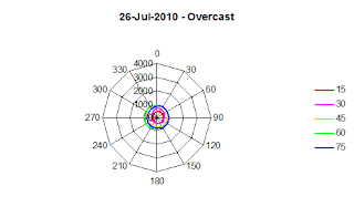
Operation consisted of setting the altitude to 15, 30, 45, 60 or 75 degrees, then rotating the instrument from 0 to 330 degrees in 30 degree increments and recording the resistance of the light dependent resistor.

The light dependent resistor has typical resistance of 20k at 100 lux. A simple calibration gave the relationship between resistance an luminescence of:


The results should be treated as relative irradiance which are consistent for the experiment, but are unlikely to represent accurate absolute values.

Overcast Sky - 26-Jul-2010 15:00: The irradiance increased slightly with altitude, but was relatively constant with azimuth.  The cloud was thick and low, there was a small break to the northeast, hence the higher irradiance in that direction:


The conclusion drawn from this observation is that irradiance from an overcast sky is more or less uniformly distributed around the sky, albeit at a level much attenuated from that expected under clear sky conditions.

Broken Cloud - 27-Jul-2010 14:00:  The early afternoon sky consisted of broken cloud, with the sun 
occasionally visible through the cloud.  Compared to the overcast sky the day before, there was significantly greater irradiance in the part of the sky in which the Sun was located.


Typically, in our part of the world, cloud described as broken, is a discrete layer and can sometimes have similar appearance to an overcast sky with only occasional glimpses of the blue sky above. This was the case on the day these readings were taken. There is an increase in irradiance in the direction of the Sun, but a significant amount of irradiance is coming from the sky as a whole.

Few Clouds - 28-Jul-2010 11:30:  As so often happens when there are a few clouds in the sky, there was some fluctuation in the readings. The maximum irradiance was to the south east at an elevation of 45 to 60 degrees.

The irradiance under a sky with a few clouds is similar to that of a clear sky with exception that there may be short periods of attenuation.

Clear Sky - 16-Aug-2010 15:00 - The irradiance is clearly coming from the sun's disk:


Under a clear sky the maximum irradiance received by a device is when it is pointing directly at the Sun. In this case the maximum irradiance was around 230 degrees at an altitude of 45 degrees which is close to the altitude and azimuth predicted by Sun-Earth geometry.

Friday, 26 April 2019

Doris B - Instrumentation

It’s a sad fact that almost everything I make gets built at least twice.  I’m trying to figure out what needs to go into the wind turbine’s “power box” and how it’s going to fit, then I’ll rebuild it so it looks less like a building site and use components with appropriate values.


It monitors the rectified output of the generator, the voltage across the load and the current through it.  This allows the power generated and being delivered to the load to be estimated.  A Fourier transform is used to determine the rotational speed.  The original intention was to work with AC output of the generator, but it proved a lot simpler to work with DC throughout the whole system.
The Arduino Nano has exceeded expectations, a previous attempt used op-amps and many other components, however, this time around, the only components used in the instrumentation are resistors for voltage divides and zenor diodes for protection.  voltages from three measurement points are fed to the Nano’s ADC.  After some processing with a couple of blocks of Python code running on a Raspberry Pi, the output looks like this:

Testing is being done using a 47 ohm resistor as a load, this keeps the current low but at the expense of high voltage on the upside of the regulator.  When a battery pack is used as a load, the voltages look a little more sensible.  Still some work to do, but the basic design is in place.
The next task is to determine if pulse width modulation can be used to control the load, if so, if so, it may be possible to optimise performance.  Ideally, I want the rotor to start to turn at 4 m/s, but the high torque of a large load may prevent this.  Maybe if the duty cycle is 0 when the turbine starts, it can be increased as the rotational speed increases.  Also, it can be adjusted to take account of low wind speeds.  All that comes after I’ve soldered the bits together.

Saturday, 20 April 2019

Doris B - Power Curve(2)

Progress (and more to learn and some bugs to find).  The Arduino captured a one minute time series of the voltage across a 22 ohm resistor attached to the generator’s output terminals whilst it was hand cranked.  The load on the crank varies during a rotation so there are constant variations in speed and this can be seen in the time-series, the flywheel effect of the wind turbine’s rotor will probably have a smoothing effect.  The circuity between generator and the ADC needs to include a zenor diode to provide some protection for the chip, once that’s in place, the DC biasing can be setup sensibly.  However, the time series was good enough to passed through a Fourier Transform routine which allowed the rotational speed to be estimated.

The speed and voltage data can then be combined into a power curve, the variations in power are due to uneven cranking.  The 22 ohm resistor was chosen because I had one in a box somewhere.  To get peak performance from the generator will require matching the impedance of the load to the impedance of the generator.  The planned load is a USB power pack.


Whilst messing with electronics and Fourier transforms has been instructive, so too has hand cranking the generator, clearly the torque required varies with the value of the resistor, with a 10 ohm resistor the torque required almost pulls the generator of its mounting.
So on the next trip to the beach, I’ll take a bag of resistors and see how they effect the ability of wind to turn the rotor.

Wednesday, 17 April 2019

Doris B - Power Curve(1)

In order to match the rotor to the generator, it is necessary to understand the behaviour of both. The first step is to grab data, starting with the generator because this can be done on the workbench rather than the beach. Much the same solution can be used for both. Currently, the instrumentation is an Arduino Nano which provides analogue to digital conversion (ADC) and a Raspberry Pi for processing. Electricity and electronics were part of my OND but that was a long time ago, so setting up the tests involved a little vexation, but eventually a Python programme managed to capture a sample of the output of the generator.


Two things became apparent, first the output of the generator is complex and not a simple sine wave, Secondly the starting torque increased significantly from the open circuit value when a resistor was placed across the terminals.


The next step is to analyse the data, the plan is to use a Fourier transform to determine the rotational speed and the area under the curve will provide the energy generated, putting the two together will provide a power curve (I hope). The Ardunio is a brilliant tool and may offer a solution to the high starting torque. If pulse width modulation is applied to the load, the turbine can start with no load and as speed increases the load on it is increased, this in turn could provide a means of optimising performance.

Friday, 12 April 2019

Doris B - First outing

 On Wednesday evening I took Doris B up to Green Ridge and assembled it.  The wind speed was  roughly 5 - 7 m/s.  Whilst held aloft, the rotor was 2.5m above the ground, it turned smoothly and quietly, which was pleasing, an earlier version had struggled to turn at 10 m/s, so progress is being made.  The next step is understand the relationship between the rotor and the generator,  The speed of this type or rotor is proportional to the wind speed and it is important that the rotor turns fast enough for the generator to produce a useful output.  On returning home I ordered some bridge rectifiers and  an Arduino Nano.  The first use of these will be to obtain a power curve for the generator.

My favourite place for messing with this stuff is on the beach at Aldrington, when the wind is from the SW there is little turbulence.  Most of the other people are beach fishermen and we occasionally swap observations on the state of the sea.  There was a curious incident at Green Ridge, a dog walker scooped up his spaniel, carried it over to my rucksack and let the dog have a good sniff, then walked off carrying the dog, I said "good evening" politely.

Wednesday, 10 April 2019

Doris B - Trial Assembly

10-April-2019 - Completed the partial assembly of the Doris B5/6 small vertical axis wind turbine this morning before giving it a trial outing on the Downs later today. 


The objectives of the initial trials are to determine if it rotates in a wind of 5 m/s and does not disintegrate at 10 m/s. If it survives, the next step will be add some instrumentation and to try and figure out how it works. The design is based on some maths, guesswork and wishful thinking. There have been four previous versions, mostly made of Meccano and sawn up bits of plastic pipe, this one is mainly made of wood. This is not a finished design but part of a process of learning how to make small wind turbines for rural and urban environments, hopefully the design will evolve. The objective for this series is an output of 2.5 watts (similar to a standard USB port) at 5 m/s.